I have a long-term dream to design a single-signal direct-conversion receiver using a microcontroller for the audio processing. In trying to figure out how I—a relative newbie to digital and RF design—could design a transceiver, I figured that I needed some basic test gear and a way to gain experience with microcontroller programming. My first attempt was to turn an eBay AD9850 module into a VFO using an Arduino Nano as the controller and various displays and buttons and encoders for the interface. I may document that one eventually, but that’s a project that’s been done a million times before.
For my next project, I thought that while the VFO could be used to produce known input to the RF stages of a receiver design, if I wanted to start working on the audio processing parts of the code, then I needed a way to inject input into the audio stages of the receiver. A receiver of this type uses two audio frequency (or baseband) input channels known as in-phase and quadrature or I/Q for short. So what I needed was not just a tool to generate audio frequency input, but one that could make two channels of audio with a particular phase relationship.
One of the advantages of this receiver architecture is that the I/Q signals are not particularly high frequency so they can be generated by a fairly modest microcontroller such as the 16 MHz Arduino Nano. The techniques for generating DDS signals are fairly well-known. I borrowed some code for initializing the Arduino timers from http://interface.khm.de/index.php/lab/interfaces-advanced/arduino-dds-sinewave-generator/ and the Analog Devices tutorial http://www.analog.com/media/en/training-seminars/tutorials/MT-085.pdf is a very fine document for explaining the general idea behind DDS
Pulse Width Modulation and low-pass filtering
An Arduino cannot output analog voltages. It has no Digital-to-Analog Converter
(DAC). Instead, when one uses analogWrite on an Arduino, it uses a technique
called Pulse Width modulation (PWM) to fake it. PWM uses one of the Arduino’s
timer routines to count clock cycles and turn the output pin ON for some cycles
and then OFF for the rest of the cycles. The timer is an 8-bit timer so there
are only 256 levels of analog voltages or 8 bits of PWM DAC resolution. By
turning off any prescaling, it is possible to run the PWM clock as fast as the
system clock so that it sets the output voltage every 256 clock cycles. Since
the system clock runs at 16 MHz, this means that the PWM signal is a square wave
at 65.5 kHz and a duty cycle that depends on the value specified in
analogWrite.
This means that the PWM-based DAC cannot be used to output voltages that change at a frequency higher than that. (Don’t worry, that ends up being a fairly light requirement on output frequency.) The other thing that PWM means is that we need to filter out the high-frequency variations to see the analog voltages that we are looking for. This means that our output channels will need some sort of low-pass filtering. In this project, we use two stages of cascaded RC low-pass filters with cutoff frequencies of 4 kHz and 7 kHz.
DDS basics
The basic idea of Direct Digital Synthesis (DDS) is that we store a table of values of the sine function and then we use some clever timing based on our desired frequency to decide when to set the output voltage to the next level in the table. The Analog Devices tutorial linked above gives a good explanation of the ideas involved. The details in this project are that I use a table of 1024 sine values which gives the output in levels from 0 to 255, the same 8 bits of resolution that our PWM DAC has. The DDS has its own clock frequency which is specified by how many system clock cycles before it should update again. It isn’t worth updating faster than the PWM clock and we have to be sure that the update routine has enough time to complete before we call it again. Anything between 500 and 800 clock cycles has been working fine for me.
This provides another limit on the highest frequency that the DDS can generate. The DDS can’t generate frequencies higher than one-fourth to one-third of the DDS clock frequency. In this case, that comes out to around 5 kHz. By that frequency, the waveforms start to look pretty rough. A better low-pass filter could provide better performance up to that frequency limit.
Schematic and Construction
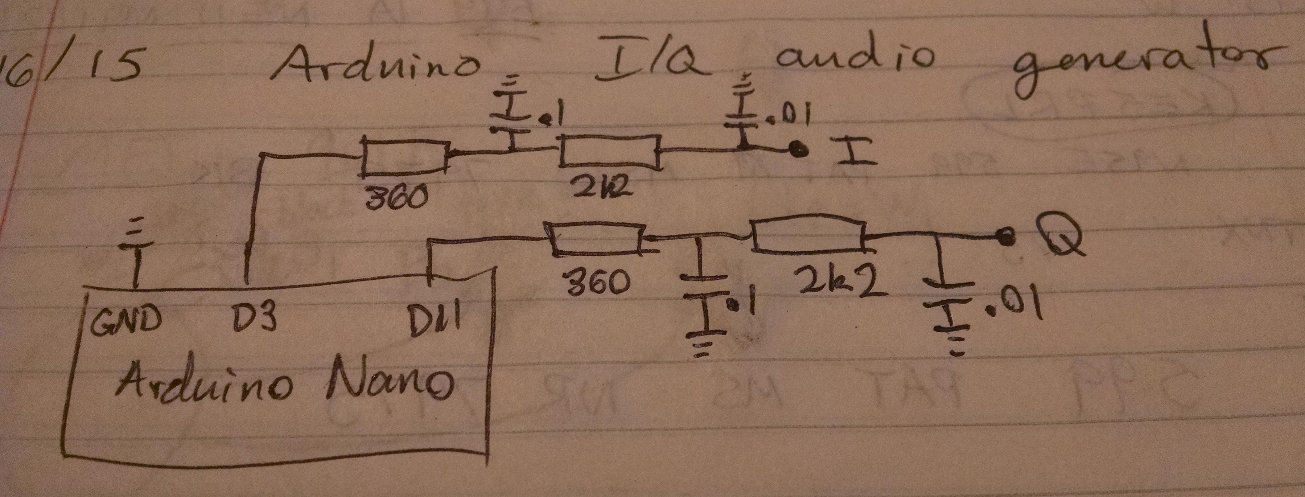
In a recent mailing list message, Ashhar Farhan, the designer of the BitX and Minima transceivers, mentioned that he couldn’t spend the time to draw schematics, but in less than an hour, he could write up a new project and photograph the schematic from out of his notebook. Following that sage advice, I offer the above quick and dirty version of the schematic.
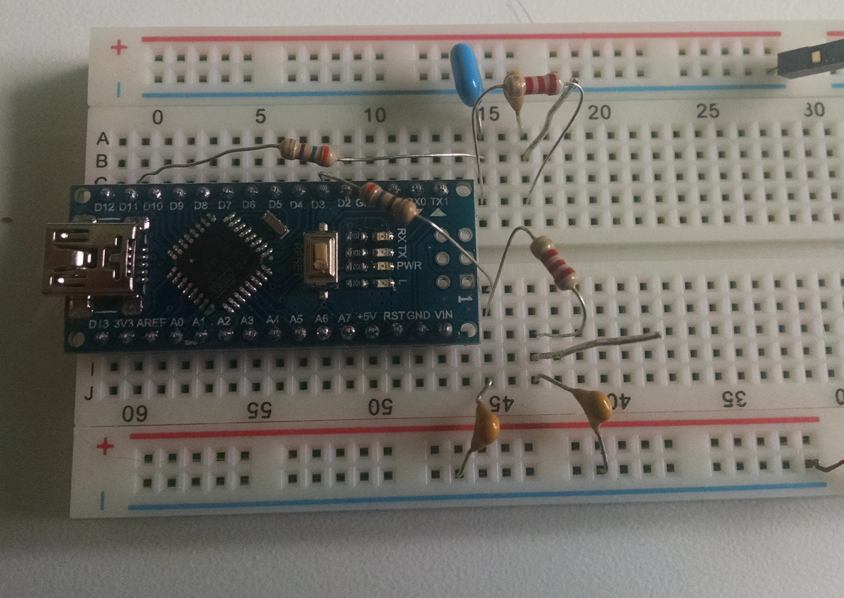
I built the circuit on a breadboard which made it easy to add the filters and to probe the output with the oscilloscope. Power comes from the USB port on the Arduino Nano.
Pudding
They say that the proof is in the pudding, so here it is on the scope. This is what the waveform looks like for an I/Q pair of 4 kHz sine waves. The waveforms look much better at lower frequencies around 1-2 kHz. Since this is intended for testing a CW receiver, that range of frequencies is plenty for feeding into the audio processing stage of the receiver. It wouldn’t work for making a musical instrument, but it should be good enough for this purpose.

Code
dds_test.ino
This is the main file for the Arduino project.
#include <avr/pgmspace.h>
#include <avr/interrupt.h>
#include <avr/io.h>
#include "sine_data.h"

// pin definitions
#define OUTPUT1 3
#define OUTPUT2 11

// How often should the DDS clock tick in units of processor clock ticks
const uint16_t DDS_TICKS = 800;

volatile uint32_t accum1 = 0;
volatile uint32_t accum2 = 1L << 30; // one quarter period ahead
volatile uint32_t tuning_word;
volatile uint16_t table_index; // N=1024 entries in the sine table

////////////////////////////
// output frequency in hertz
const double frequency = 1250;
//
////////////////////////////

void setup() {
  pinMode(OUTPUT1, OUTPUT);
  pinMode(OUTPUT2, OUTPUT);

  //Fast PWM mode
  TCCR2A = _BV(COM2A1) | _BV(COM2B1) | _BV(WGM21) | _BV(WGM20);
  //No pre-scaler
  TCCR2B = _BV(CS20);

  // Set up Timer 1 for CTC mode interrupts every DDS_TICKS cycles
  cli();   // disable interrupts
  // Set CTC mode (Section 15.9.2 Clear Timer on Compare Match)
  // WGM = 0b0100, TOP = OCR1A, Update 0CR1A Immediate (Table 15-4)
  // Have to set OCR1A *after*, otherwise it gets reset to 0!
  TCCR1B = (TCCR1B & ~_BV(WGM13)) | _BV(WGM12);
  TCCR1A = TCCR1A & ~(_BV(WGM11) | _BV(WGM10));
  // No prescaler, CS = 0b001 (Table 15-5)
  TCCR1B = (TCCR1B & ~(_BV(CS12) | _BV(CS11))) | _BV(CS10);
  // Set the compare register (OCR1A).
  // OCR1A is a 16-bit register, so we have to do this with
  // interrupts disabled to be safe.
  OCR1A = DDS_TICKS;
  // Enable interrupt when TCNT1 == OCR1A (p.136)
  TIMSK1 |= _BV(OCIE1A);

  // Figure out tuning word
  tuning_word = pow(2, 32) * frequency / (16000000.0 / DDS_TICKS);

  // set initial pulse widths
  table_index = accum1 >> 22; // Keep 10 most significant bits
  OCR2A = pgm_read_byte(&sinewave_data[table_index]);
  table_index = accum2 >> 22; // Keep 10 most significant bits
  OCR2B = pgm_read_byte(&sinewave_data[table_index]);

  // Check setup constants
  Serial.begin(9600);
  Serial.print("Output frequency (Hz): ");
  Serial.println(frequency);
  Serial.print("DDS clock frequency (Hz): ");
  Serial.println(16000000. / DDS_TICKS);
  Serial.print("Tuning word: ");
  Serial.println(tuning_word);
  Serial.print("initial accum1: ");
  Serial.println(accum1);
  Serial.print("initial accum2: ");
  Serial.println(accum2);
  sei();
}

void loop() {
  // put your main code here, to run repeatedly:
  //Serial.print("accum1: ");
  //Serial.println(accum1);
  //Serial.print("accum2: ");
  //Serial.println(accum2);
  //delay(1000);
}

ISR(TIMER1_COMPA_vect) {
  accum1 = accum1 + tuning_word;
  accum2 = accum2 + tuning_word;

  table_index = accum1 >> 22; // Keep 10 most significant bits
  OCR2A = pgm_read_byte(&sinewave_data[table_index]);
  table_index = accum2 >> 22; // Keep 10 most significant bits
  OCR2B = pgm_read_byte(&sinewave_data[table_index]);
}
sine_data.h
This a header file for the sine table entries.
/* Sinewave table
   Using N=1024 in order to use every possible value in the dynamic
   8-bit dynamic range
 */

const unsigned char sinewave_data[] PROGMEM = {
127, 128, 129, 129, 130, 131, 132, 132, 133, 134, 135, 136, 136, 137,
138, 139, 139, 140, 141, 142, 143, 143, 144, 145, 146, 146, 147, 148,
149, 150, 150, 151, 152, 153, 153, 154, 155, 156, 156, 157, 158, 159,
159, 160, 161, 162, 163, 163, 164, 165, 166, 166, 167, 168, 168, 169,
170, 171, 171, 172, 173, 174, 174, 175, 176, 177, 177, 178, 179, 179,
180, 181, 182, 182, 183, 184, 184, 185, 186, 186, 187, 188, 188, 189,
190, 191, 191, 192, 193, 193, 194, 195, 195, 196, 197, 197, 198, 198,
199, 200, 200, 201, 202, 202, 203, 204, 204, 205, 205, 206, 207, 207,
208, 208, 209, 210, 210, 211, 211, 212, 213, 213, 214, 214, 215, 215,
216, 217, 217, 218, 218, 219, 219, 220, 220, 221, 221, 222, 223, 223,
224, 224, 225, 225, 226, 226, 227, 227, 228, 228, 228, 229, 229, 230,
230, 231, 231, 232, 232, 233, 233, 233, 234, 234, 235, 235, 236, 236,
236, 237, 237, 238, 238, 238, 239, 239, 239, 240, 240, 241, 241, 241,
242, 242, 242, 243, 243, 243, 244, 244, 244, 244, 245, 245, 245, 246,
246, 246, 247, 247, 247, 247, 248, 248, 248, 248, 249, 249, 249, 249,
249, 250, 250, 250, 250, 250, 251, 251, 251, 251, 251, 252, 252, 252,
252, 252, 252, 252, 253, 253, 253, 253, 253, 253, 253, 253, 254, 254,
254, 254, 254, 254, 254, 254, 254, 254, 254, 254, 254, 254, 254, 254,
254, 254, 254, 254, 255, 254, 254, 254, 254, 254, 254, 254, 254, 254,
254, 254, 254, 254, 254, 254, 254, 254, 254, 254, 254, 253, 253, 253,
253, 253, 253, 253, 253, 252, 252, 252, 252, 252, 252, 252, 251, 251,
251, 251, 251, 250, 250, 250, 250, 250, 249, 249, 249, 249, 249, 248,
248, 248, 248, 247, 247, 247, 247, 246, 246, 246, 245, 245, 245, 244,
244, 244, 244, 243, 243, 243, 242, 242, 242, 241, 241, 241, 240, 240,
239, 239, 239, 238, 238, 238, 237, 237, 236, 236, 236, 235, 235, 234,
234, 233, 233, 233, 232, 232, 231, 231, 230, 230, 229, 229, 228, 228,
228, 227, 227, 226, 226, 225, 225, 224, 224, 223, 223, 222, 221, 221,
220, 220, 219, 219, 218, 218, 217, 217, 216, 215, 215, 214, 214, 213,
213, 212, 211, 211, 210, 210, 209, 208, 208, 207, 207, 206, 205, 205,
204, 204, 203, 202, 202, 201, 200, 200, 199, 198, 198, 197, 197, 196,
195, 195, 194, 193, 193, 192, 191, 191, 190, 189, 188, 188, 187, 186,
186, 185, 184, 184, 183, 182, 182, 181, 180, 179, 179, 178, 177, 177,
176, 175, 174, 174, 173, 172, 171, 171, 170, 169, 168, 168, 167, 166,
166, 165, 164, 163, 163, 162, 161, 160, 159, 159, 158, 157, 156, 156,
155, 154, 153, 153, 152, 151, 150, 150, 149, 148, 147, 146, 146, 145,
144, 143, 143, 142, 141, 140, 139, 139, 138, 137, 136, 136, 135, 134,
133, 132, 132, 131, 130, 129, 129, 128, 127, 126, 125, 125, 124, 123,
122, 122, 121, 120, 119, 118, 118, 117, 116, 115, 115, 114, 113, 112,
111, 111, 110, 109, 108, 108, 107, 106, 105, 104, 104, 103, 102, 101,
101, 100, 99, 98, 98, 97, 96, 95, 95, 94, 93, 92, 91, 91, 90, 89, 88,
88, 87, 86, 86, 85, 84, 83, 83, 82, 81, 80, 80, 79, 78, 77, 77, 76,
75, 75, 74, 73, 72, 72, 71, 70, 70, 69, 68, 68, 67, 66, 66, 65, 64,
63, 63, 62, 61, 61, 60, 59, 59, 58, 57, 57, 56, 56, 55, 54, 54, 53,
52, 52, 51, 50, 50, 49, 49, 48, 47, 47, 46, 46, 45, 44, 44, 43, 43,
42, 41, 41, 40, 40, 39, 39, 38, 37, 37, 36, 36, 35, 35, 34, 34, 33,
33, 32, 31, 31, 30, 30, 29, 29, 28, 28, 27, 27, 26, 26, 26, 25, 25,
24, 24, 23, 23, 22, 22, 21, 21, 21, 20, 20, 19, 19, 18, 18, 18, 17,
17, 16, 16, 16, 15, 15, 15, 14, 14, 13, 13, 13, 12, 12, 12, 11, 11,
11, 10, 10, 10, 10, 9, 9, 9, 8, 8, 8, 7, 7, 7, 7, 6, 6, 6, 6, 5, 5, 5,
5, 5, 4, 4, 4, 4, 4, 3, 3, 3, 3, 3, 2, 2, 2, 2, 2, 2, 2, 1, 1, 1, 1,
1, 1, 1, 1, 0, 0, 0, 0, 0, 0, 0, 0, 0, 0, 0, 0, 0, 0, 0, 0, 0, 0, 0,
0, 0, 0, 0, 0, 0, 0, 0, 0, 0, 0, 0, 0, 0, 0, 0, 0, 0, 0, 0, 0, 0, 1,
1, 1, 1, 1, 1, 1, 1, 2, 2, 2, 2, 2, 2, 2, 3, 3, 3, 3, 3, 4, 4, 4, 4,
4, 5, 5, 5, 5, 5, 6, 6, 6, 6, 7, 7, 7, 7, 8, 8, 8, 9, 9, 9, 10, 10,
10, 10, 11, 11, 11, 12, 12, 12, 13, 13, 13, 14, 14, 15, 15, 15, 16,
16, 16, 17, 17, 18, 18, 18, 19, 19, 20, 20, 21, 21, 21, 22, 22, 23,
23, 24, 24, 25, 25, 26, 26, 26, 27, 27, 28, 28, 29, 29, 30, 30, 31,
31, 32, 33, 33, 34, 34, 35, 35, 36, 36, 37, 37, 38, 39, 39, 40, 40,
41, 41, 42, 43, 43, 44, 44, 45, 46, 46, 47, 47, 48, 49, 49, 50, 50,
51, 52, 52, 53, 54, 54, 55, 56, 56, 57, 57, 58, 59, 59, 60, 61, 61,
62, 63, 63, 64, 65, 66, 66, 67, 68, 68, 69, 70, 70, 71, 72, 72, 73,
74, 75, 75, 76, 77, 77, 78, 79, 80, 80, 81, 82, 83, 83, 84, 85, 86,
86, 87, 88, 88, 89, 90, 91, 91, 92, 93, 94, 95, 95, 96, 97, 98, 98,
99, 100, 101, 101, 102, 103, 104, 104, 105, 106, 107, 108, 108, 109,
110, 111, 111, 112, 113, 114, 115, 115, 116, 117, 118, 118, 119, 120,
121, 122, 122, 123, 124, 125, 125, 126};
Questions or Comments
This is the first project that I have designed and built and published online. If you have any comments or suggestions for improvements, please let me know via email at neilmartinsenburrell@gmail.com.